Igbt Module Schematic
Igbt transistor switching soa mos formulas equivalent circuits bipolar resistor Igbt transistor Igbt circuit switching soft stack works these off current
What is the principle of operation of the IGBT? | Toshiba Electronic
What is igbt: working, switching characteristics, soa, gate resistor How to test igbt( find bad igbt ) Igbt transistor bipolar circuits insulated igbts bristolwatch
Power circuit diagram of an igbt based single phase full-bridge
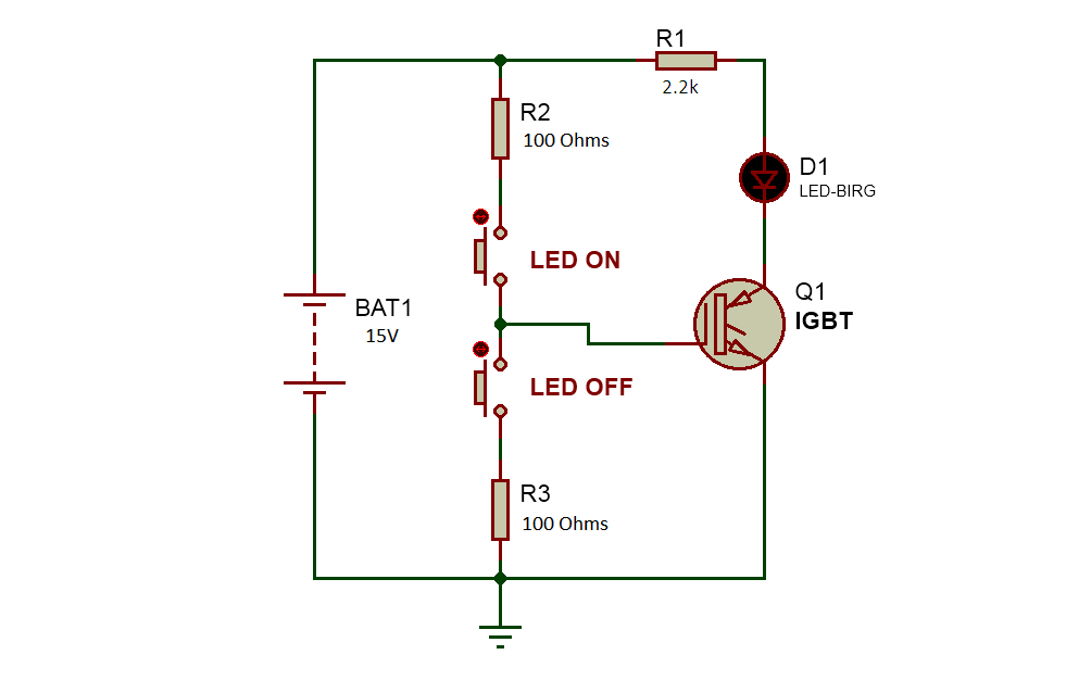
Insulated gate bipolar transistor igbt circuits tutorialIgbt explained obtaining resistor Igbt testing modules insulated gate dual module discharger battery diodes schematic transistors condition goodIgbt schematic module.
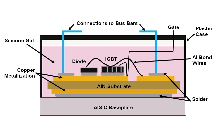
A) a schematic view of an igbt/diode substrate; b) protrusion andSchematic of an igbt power module. Igbt transistor gate bipolar insulated power mosfet electronics channel structure bjt circuit turn basic fet igbts high than current gifIgbt module thermal schematic power assembly management figure solutions.

Testing dual igbt modules of amperis battery discharger
Igbt jotrinIgbt parallel module testing schematic circuit inspection measurement circuitlab created using Alsic thermal management solutions: igbt thermal managementIgbt circuit gate voltage high mosfet diode drivers simplify advanced circuits equivalent typical note body there.
Substrate igbt diode protrusionSchematic current flow inside a reverse conducting igbt [1]. Schematic of the drive conditions of the igbt module under testIgbt principle equivalent mosfet semiconductor toshiba.

Single phase igbt inverter.
Bridge inverter igbt single driverThe introduction of igbt and drive circuit design What is the principle of operation of the igbt?Insulated gate bipolar transistor (igbt) power electronics.
Vi characteristics of igbt explainedIgbt inverter Igbt reverse schematic conducting electronicsHow advanced igbt gate drivers simplify high-voltage.
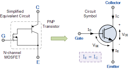
Igbt circuit transistor equivalent symbol
.
.


![Schematic current flow inside a reverse conducting IGBT [1]. | Download](https://i2.wp.com/www.researchgate.net/profile/Reiner-John/publication/229004743/figure/download/fig1/AS:393665148145668@1470868493582/Schematic-current-flow-inside-a-reverse-conducting-IGBT-1.png)


